Mounting and Wiring of I/O Terminals
Jump to a section on this page:
Instructions for ESD Protection
-
-
Desctruction of the devices by electrostatic discharge possible!
The devices contain components at risk from electrostatic discharge caused by improper handling.
- Please ensure you are electrostatically discharged and avoid touching the contacts of the device directly.
- Avoid contact with highly insulating materials (synthetic fibers, plastic film, etc.).
- Surroundings (working place, packaging, and personnel) should be grounded properly when handling the devices.
- Each assembly must be terminated at the right hand end with an AKT2G-EM-000-000 bus end cap to ensure the protection class and ESD protection.
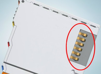
Figure 8-57: Spring contacts of the I/O components.
Installation on mounting rails
-
-
Risk of electric shock and damage of device!
Bring the bus terminal system into a safe, powered down state before starting installation, disassembly or wiring of the bus terminals!
Assembly
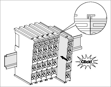
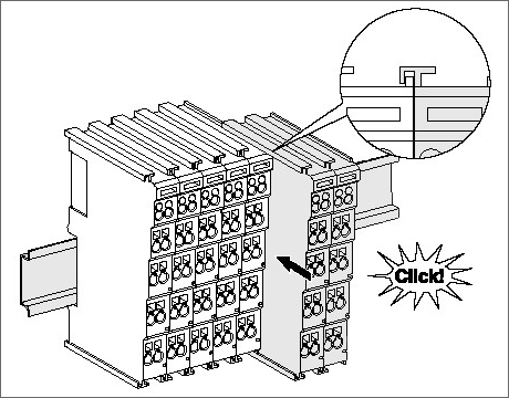
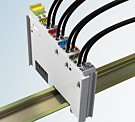
Figure 8-58: Attaching on mounting rail
The bus coupler and bus terminals are attached to commercially available 35 mm mounting rails (DIN rails according to EN 60715) by applying slight pressure:
- First attach the fieldbus coupler to the mounting rail.
- The bus terminals are now attached on the right-hand side of the fieldbus coupler. Join the components with tongue and groove and push the terminals against the mounting rail, until the lock clicks onto the mounting rail.
If the terminals are clipped onto the mounting rail first and then pushed together without tongue and groove, the connection will not be operational! When correctly assembled, no significant gap should be visible between the housings.
-
-
Fixing of mounting rails
The locking mechanism of the terminals and couplers extends to the profile of the mounting rail. At the installation, the locking mechanism of the components must not come into conflict with the fixing bolts of the mounting rail. To mount the mounting rails with a height of 7.5 mm under the terminals and couplers, you should use flat mounting connections (e.g. countersunk screws or blind rivets).
Disassembly
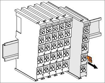
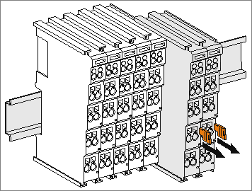
Figure 8-59: Disassembling of terminal
Each terminal is secured by a lock on the mounting rail, which must be released for disassembly:
- Pull the terminal by its orange-colored lugs approximately 1 cm away from the mounting rail. In doing so for this terminal the mounting rail lock is released automatically and you can pull the terminal out of the bus terminal block easily without excessive force.
- Grasp the released terminal with thumb and index finger simultaneous at the upper and lower grooved housing surfaces and pull the terminal out of the bus terminal block.
Connections within a bus terminal block
The electric connections between the Bus Coupler and the Bus Terminals are automatically realized by joining the components:
- The six spring contacts of the E-Bus/K-Bus deal with the transfer of the data and the supply of the Bus Terminal electronics.
- The power contacts deal with the supply for the field electronics and thus represent a supply rail within the bus terminal block. The power contacts are supplied via terminals on the Bus Coupler (up to 24 V) or for higher voltages via power feed terminals.
Power Contacts
During the design of a bus terminal block, the pin assignment of the individual Bus Terminals must be taken account of, since some types (e.g. analog Bus Terminals or digital 4-channel Bus Terminals) do not or not fully loop through the power contacts. Power Feed Terminals (AKT2G-PSF-024-000) interrupt the power contacts and thus represent the start of a new supply rail.
PE power contact
The power contact labeled PE can be used as a protective earth. For safety reasons this contact mates first when plugging together, and can ground short-circuit currents of up to 125 A.
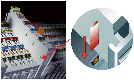
Figure 8-60: Power contact on left side
-
-
Possible damage of the device
Note that, for reasons of electromagnetic compatibility, the PE contacts are capacitatively coupled to the mounting rail. This may lead to incorrect results during insulation testing or to damage on the terminal (e.g. disruptive discharge to the PE line during insulation testing of a consumer with a nominal voltage of 230 V). For insulation testing, disconnect the PE supply line at the Bus Coupler or the Power Feed Terminal! In order to decouple further feed points for testing, these Power Feed Terminals can be released and pulled at least 10 mm from the group of terminals.
-
-
Risk of electric shock!
The PE power contact must not be used for other potentials!
Installation instructions for enhanced mechanical load capacity
-
-
Risk of injury through electric shock and damage to the device!
Bring the Bus Terminal system into a safe, de-energized state before starting mounting, disassembly or wiring of the Bus Terminals!
Additional checks
The terminals have undergone the following additional tests:
| Verification | Explanation |
|---|---|
| Vibration | 10 frequency runs in 3 axes |
| 6 Hz < f < 60 Hz displacement 0.35 mm, constant amplitude | |
| 60.1 Hz < f < 500 Hz acceleration 5 g, constant amplitude | |
| Shocks | 1000 shocks in each direction, in 3 axes |
| 25 g, 6 ms |
Additional installation instructions
For terminals with enhanced mechanical load capacity, the following additional installation instructions apply:
- The enhanced mechanical load capacity is valid for all permissible installation positions
- Use a mounting rail according to EN 60715 TH35-15
- Fix the terminal segment on both sides of the mounting rail with a mechanical fixture, e.g. an earth terminal or reinforced end clamp
- The maximum total extension of the terminal segment (without coupler) is:
64 terminals (12 mm mounting with) or 32 terminals (24 mm mounting with) - Avoid deformation, twisting, crushing and bending of the mounting rail during edging and installation of the rail
- The mounting points of the mounting rail must be set at 5 cm intervals
- Use countersunk head screws to fasten the mounting rail
- The free length between the strain relief and the wire connection should be kept as short as possible. A distance of approx. 10 cm should be maintained to the cable duct.
Connection
Connection system
-
-
Risk of electric shock and damage of device!
Bring the bus terminal system into a safe, powered down state before starting installation, disassembly or wiring of the bus terminals!
Overview
The Bus Terminal system offers different connection options for optimum adaptation to the respective application:
- The terminals of AKT2G and AKT series with standard wiring include electronics and connection level in a single enclosure.
Standard wiring (AKT2G/AKT-xx)
The terminals of AKT2G and AKT series have been tried and tested for years.
They feature integrated screwless spring force technology for fast and simple assembly.
Wiring
-
-
Risk of electric shock and damage of device!
Bring the bus terminal system into a safe, powered down state before starting installation, disassembly or wiring of the Bus Terminals!
Terminals for standard wiring AKT2G-xx/AKT-xx
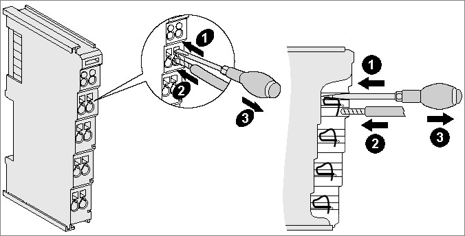
Figure 8-62: Connecting a cable on a terminal point
Up to eight terminal points enable the connection of solid or finely stranded cables to the Bus Terminal. The terminal points are implemented in spring force technology. Connect the cables as follows:
- Open a terminal point by pushing a screwdriver straight against the stop into the square opening above the terminal point. Do not turn the screwdriver or move it alternately (don't toggle).
- The wire can now be inserted into the round terminal opening without any force.
- The terminal point closes automatically when the pressure is released, holding the wire securely and permanently.
See the following table for the suitable wire size width.
Terminal Housing
AKT2G-xx, AKT-xx
Wire size width (single core wires) 0.08 ... 2.5 mm2 Wire size width (fine-wire conductors) 0.08 ... 2.5 mm2 Wire size width (conductors with a wire end sleeve) 0.14 ... 1.5 mm2 Wire stripping length 8 ... 9 mm
Shielding
-
-
Shielding
Encoder, analog sensors and actors should always be connected with shielded, twisted paired wires.
-
-
Observe the special conditions for the intended use of Kollmorgen fieldbus components with extended temperature range (ET) in potentially explosive areas (directive 2014/34/EU)!
- The certified components are to be installed in a suitable housing that guarantees a protection class of at least IP54 in accordance with EN 60079-15! The environmental conditions during use are thereby to be taken into account!
- For dust (only the fieldbus components of certificate no. KEMA 10ATEX0075 X Issue 9): The equipment shall be installed in a suitable enclosure providing a degree of protection of IP54 according to EN 60079-0 for group IIIA or IIIB and IP6X for group IIC, taking into account the environmental conditions under which the equipment is used.
- If the temperatures during rated operation are higher than 70°C at the feed-in points of cables, lines or pipes, or higher than 80°C at the wire branching points, then cables must be selected whose temperature data correspond to the actual measured temperature values!
- Observe the permissible ambient temperature range of -25 to 60°C for the use of Kollmorgen fieldbus components with extended temperature range (ET) in potentially explosive areas!
- Measures must be taken to protect against the rated operating voltage being exceeded by more than 40% due to short-term interference voltages!
- The individual terminals may only be unplugged or removed from the Bus Terminal system if the supply voltage has been switched off or if a non-explosive atmosphere is ensured!
- The connections of the certified components may only be connected or disconnected if the supply voltage has been switched off or if a non-explosive atmosphere is ensured!
- The fuses of the AKT2G-PSF-024-000 power feed terminals may only be exchanged if the supply voltage has been switched off or if a non-explosive atmosphere is ensured!
- Address selectors and ID switches may only be adjusted if the supply voltage has been switched off or if a non-explosive atmosphere is ensured!
Installation positions
-
-
Constraints regarding installation position and operating temperature range
Please refer to the technical data for a terminal to ascertain whether any restrictions regarding the installation position and/or the operating temperature range have been specified. When installing high power dissipation terminals ensure that an adequate spacing is maintained between other components above and below the terminal in order to guarantee adequate ventilation!
Optimum installation position (standard)
The optimum installation position requires the mounting rail to be installed horizontally and the connection surfaces of the AKT2G terminals to face forward (see Figure 8-63: Recommended distances for standard installation position). The terminals are ventilated from below, which enables optimum cooling of the electronics through convection. “From below” is relative to the acceleration of gravity.
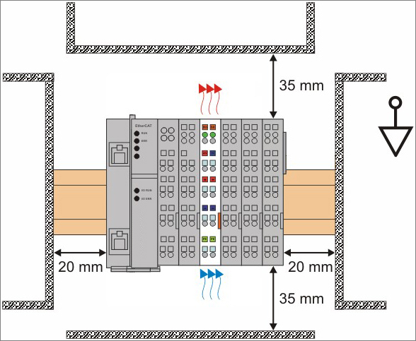
Figure 8-63: Recommended distances for standard installation position
Compliance with the distances shown in Fig. Recommended distances for standard installation position is recommended.
Other installation positions
All other installation positions are characterized by different spatial arrangement of the mounting rail - see Figure 8-64: Other installation positions.
The minimum distances to ambient specified above also apply to these installation positions.
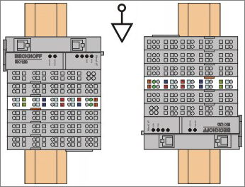
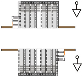
Figure 8-64: Other installation positions
Positioning of Passive Terminals
-
-
Hint for positioning of passive terminals in the bus terminal block
EtherCAT ***EtherCAT is an open, high-performance Ethernet-based fieldbus system. The development goal of EtherCAT was to apply Ethernet to automation applications which require short data update times (also called cycle times) with low communication jitter (for synchronization purposes) and low hardware costs Terminals (AKT2G-xx), which do not take an active part in data transfer within the bus terminal block are so called passive terminals. The passive terminals have no current consumption out of the E-Bus.
To ensure an optimal data transfer, you must not directly string together more than two passive terminals!
Examples for positioning of passive terminals (highlighted)
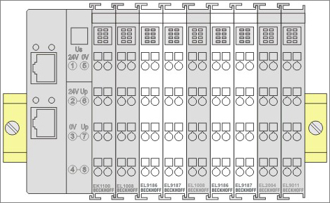
Figure 8-65: Correct positioning
Figure 8-66: Incorrect positioning
UL Notice
|
|
Application Kollmorgen EtherCAT modules are intended for use with Kollmorgen’s UL Listed EtherCAT System only. |
|
|
Examination For cULus examination, the Kollmorgen I/O System has only been investigated for risk of fire and electrical shock (in accordance with UL508 and CSA C22.2 No. 142). |
|
|
For devices with Ethernet Not for connection to telecommunication circuits. |

Basic principles
UL certification according to UL508. Devices with this kind of certification are marked by this sign:

Continuative documentation about explosion protection
-
-
Explosion protection for terminal systems
Pay also attention to the continuative documentation


